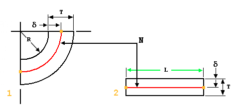
K factor a constant determined by dividing the thickness of the sheet by the location of the neutral axis which is the part of sheet metal that does not change length.
Creo sheet metal k factor.
The location of the neutral axis varies and is based on the material s physical properties and its thickness.
Overview this comprehensive suite of creo sheet metal design tools helps users create features such as walls bends punches notches forms and relief features.
With a y factor of 5 creo default the flat pattern ws 7 0354 long.
Our design engineers typically use a factor of 0 4 for our air formed press brake parts.
Creo sheet metal tutorial.
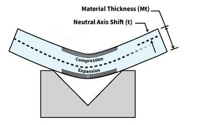
When metal is bent the top section is going to undergo compression and the bottom section will be stretched.
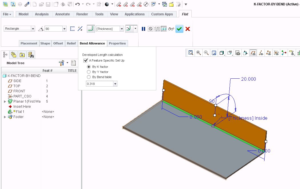
These parameters can also be set using the bend allowance area of the sheetmetal preferences dialog box.
Reference pages explaining k factor and y factor.
Sheet metal k factor hi graham i could be wrong for the latest creo 1 0 but till now i have never able to directly access that smt k factor system parameter with relations.
The k factor in sheet metal working is the ratio of the neutral axis to the material thickness.
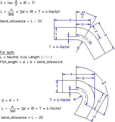
K factor in sheet metal bending is a constant used to calculate sheet metal flat length or flat pattern.
In this article we will discuss sheetmetal bend deduction bend allowance k factor y factor and sheet metal flat pattern calculations.
This video to describe setting of k factor in creo and how to change developed length of sheet metal parts.
The line where the transition from compression to stretching occurs is called the neutral axis.
The k factor is the ratio of the neutral axis location t to the material thickness mt.
I had a question on k factors for our 3 d modeling software.
K factor is an import.
The k factor is the most important and elusive variable of bending because it varies both as a function of the material and according to parameters such as angle and tooling.
The result is parametric fully associative solid models of sheet metal parts and assemblies.
Using a variety of y and k factor bend allowance calculations designers can create flat patterns of the designs.
The part of the material that bends without being compressed nor elongated.
Smt part bend allowance factor sets the value of y factor or k factor.
When you bend sheet metal the neutral axis shifts toward the inside surface of the bend.
Mathematically k factor value is equal to the ratio of position of neutral axis and sheet thickness.
Creating feature specific bend allowance using the bend allowance tab of sheet metal tools when available.


